-
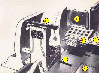
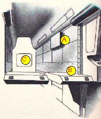
Air intake serving air conditioning and air cooling systems for rear
machinery;
-
TV driving
screen;
-
Instrument panel;
-
Rearward facing driver's seat with ejection parachute pack;
-
Selector panel for power pack attachments such as the thrusters pack conversion. These items are stored in the cabinets seen immediately above the selector panel, and which run both sides of a gangway down the length of the
vehicle;
-
Driver,
and live TV screen. The SPV can be driven from either of the twin
positions;
-
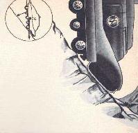
Brackets
connect the seat to the armoured door. To leave the vehicle, the overhead
ramps are extended, sliding door and attached seat sideways till exit is clear;
-
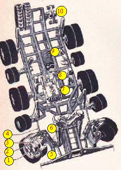
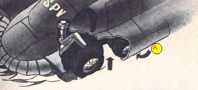
The power pack, held in position by twin clamps which raise it through a sliding panel in the floor above, when required for thrusters pack or other use;
-
Armoured
cable conducts current from the power pack to the magnetic brakes;
-
Hub
motors;
-
Magnetic disc
brake and support arm which pivots on the cantilevered bracket attached to the
main shock absorber. The square-ended box to the left of the support arm
contains the hydropneumatic ram by which the steering is effected. The
smaller wheels behind are couple to turn in unison;
-
Main shock absorber;
-
A limited-travel absorber permits wheel to tilt on rough
ground;
-
The rugged tubular
chassis;
-
Air intake and duct serving fuel cell and forward cooling
units;
-
Front flotation chamber contains buoyancy compartments (not shown) for amphibious work. Its curved profile makes it a useful fender at low speeds, but in the event of a high speed collision it will collapse giving a cushioning
effect;
-
Headlight and TV camera;
-
Main hydraulics oil
reservoir;
-
Air
intake;
-
Cantilevered chassis supporting tracks and converter for the twin aqua-jets (not
shown);
-
Motor driving tank
tracks;
-
Battery. This is a standby connected to motors in the four smaller wheels. These provide drive when the power pack is removed and the motors in the six pairs of wheels are
idle;
-
Suspension (is similar on all wheels except front pair).